Engineering
Earthing, lightning and surge protection for solar plants
Three different systems, often confused, and all three decide whether your inverters survive the monsoon.
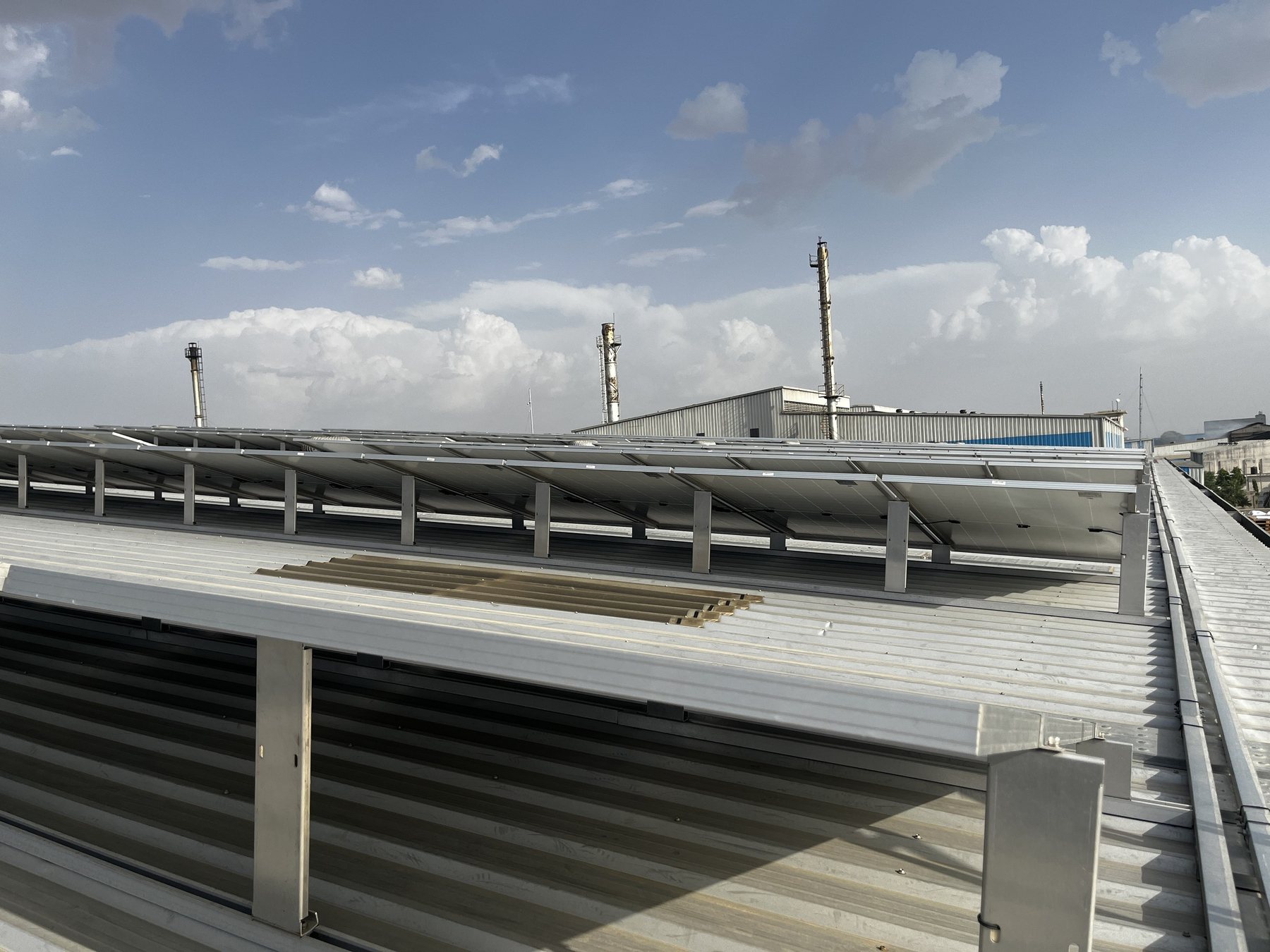
A rooftop solar plant puts a large metal structure and hundreds of metres of cable on the highest, most exposed part of a building. Earthing, lightning protection and surge protection are three different systems that are often confused, and getting them wrong can damage inverters, start fires or create shock hazards. Here is how they fit together.
Three systems, three jobs
| System | Protects against | Key standards |
|---|---|---|
| Protective earthing and bonding | Electric shock from faulty equipment; keeps all metal at the same potential | IS 3043, IEC 60364-7-712, CEA Safety Regulations 2023 |
| Lightning protection system (LPS) | Direct lightning strikes on the building or array | IS/IEC 62305 (Parts 1–4) |
| Surge protection devices (SPDs) | Voltage spikes induced by nearby lightning or switching | IEC 61643-31 (DC side), IEC 61643-11 (AC side) |
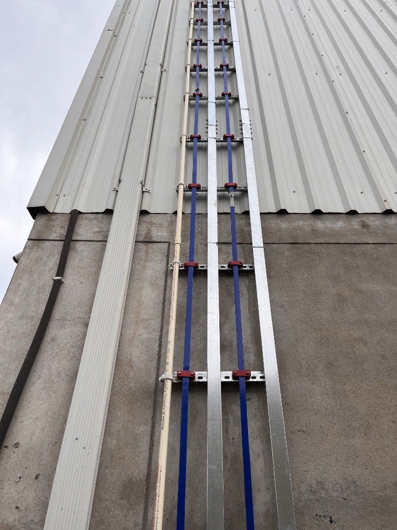
1. Earthing and equipotential bonding
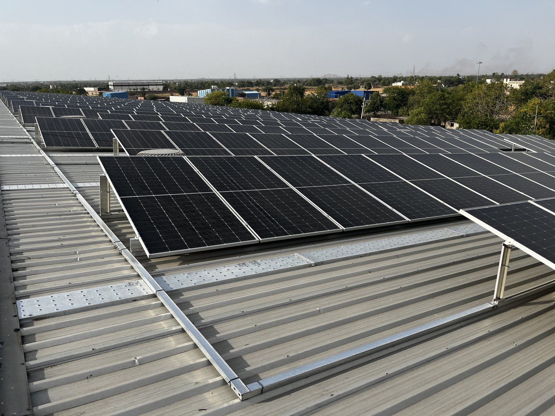
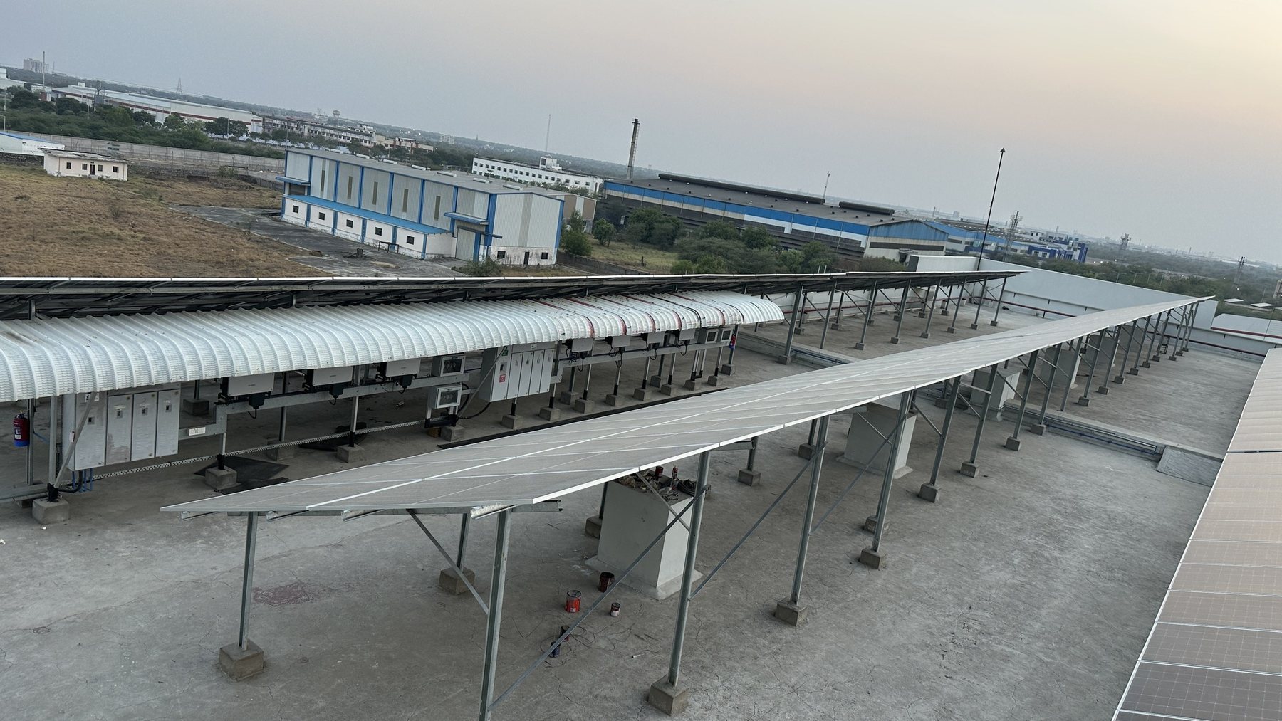
Every exposed metal part (module frames, mounting rails, cable trays, inverter and combiner enclosures) must be bonded together and to earth, so that a fault cannot leave any of it at a dangerous voltage. Good practice on a rooftop plant:
- Bond module frames to the rails using earthing clips, serrated washers or bonding jumpers approved by the module and structure makers. Anodised aluminium is an insulator; a plain bolt through an anodised rail is not a reliable bond.
- Run a continuous earth conductor (typically galvanised iron or copper strip, or a sized copper cable) along each array, bonded to every rail section.
- Separate earth pits for DC side, AC side and lightning protection, each tested, and then interconnected below ground or at a main earthing bar, so the whole installation is at one potential. Isolated, unconnected earths are a common and dangerous mistake.
- Target earth resistance is commonly specified at below 5 Ω for the system and below 1 Ω for substations in Indian tender specifications; test each pit with a proper earth tester and record the values.
- Use maintenance-free chemical earthing electrodes or conventional pipe or plate electrodes to IS 3043, with inspection chambers so the pits can be tested every year.
2. Lightning protection
Not every building needs an external LPS. IEC 62305-2 sets out a risk assessment based on lightning flash density, building size and use, and consequences of damage. Much of Maharashtra, Gujarat, eastern India and parts of Rajasthan see frequent pre-monsoon thunderstorms, and a large industrial roof with a solar array often ends up needing protection.
Where an LPS is needed:
- Air terminals (lightning arresters) are positioned so the whole array falls within their protection zone, calculated with the rolling sphere or protection angle method for the required protection class.
- Keep the separation distance. The LPS conductors should be kept a calculated separation distance (often 0.5–1 m) from the PV array and its cables. If that is impossible, the array must be bonded to the LPS, and then Type 1 SPDs become necessary because lightning current can enter the PV wiring.
- Avoid shadows. Arrester masts cast shadows across modules. Place them on the north side of arrays or at row ends.
- Down conductors run by the shortest route to dedicated, tested earth pits.
Early Streamer Emission (ESE) arresters are widely sold in India with claims of very large protection radii. They are not recognised by IEC 62305, and many engineers design to conventional air terminals for that reason.
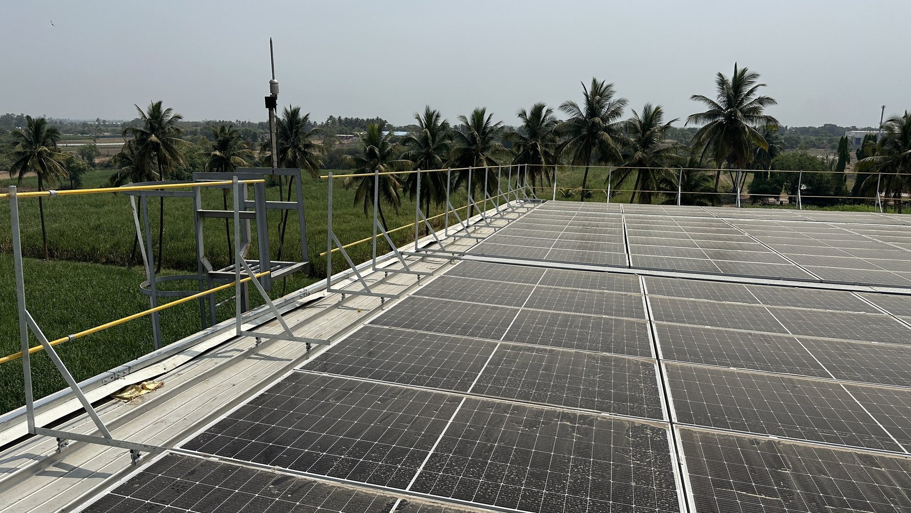
3. Surge protection
Most lightning damage to solar plants is not from direct strikes but from surges induced in long DC cables by nearby strikes. SPDs divert these surges to earth before they reach the inverter.
- DC side: PV-specific SPDs to IEC 61643-31, rated above the array's maximum open-circuit voltage at the coldest expected temperature, at the inverter DC input and, for long cable runs (more than about 10 m), also near the array.
- AC side: SPDs to IEC 61643-11 at the inverter output and the main AC distribution board.
- Type 1 vs Type 2: Type 2 SPDs (tested with an 8/20 µs waveform) handle induced surges and are the norm. Type 1 or combined Type 1+2 SPDs (10/350 µs) are needed where partial lightning current can reach the wiring, typically when the array is bonded to an external LPS.
- Short connection leads. An SPD connected with a long, looped earth wire lets most of the surge through. Keep leads as short and straight as possible.
- Check the indicators. SPDs are sacrificial. The status windows should be part of every inspection, especially after the monsoon.
The most common faults found on existing plants: module frames not bonded to anodised rails; DC, AC and lightning earth pits not interconnected; lightning arresters shading modules; and SPDs with expired status indicators that nobody has replaced.
Testing and records
At handover, you should receive earth resistance values for every pit, continuity test results for the bonding of the array, an LPS risk assessment or a statement of why one is not required, and SPD specifications. Earth pits should be retested annually, ideally before the monsoon. If your plant has none of this paperwork, we can audit it.
Sources and further reading
- CEA (Measures relating to Safety and Electric Supply) Regulations, 2023
- VIOX: DC SPD selection for solar (IEC 61643-31)
- LSP: how to select SPDs for solar systems
Standards and regulations change. Check the current edition and your state regulator before relying on any figure for a specific project.