O&M
Commissioning a solar plant properly: IEC 62446 tests, I-V curves, thermography and EL
"Commissioned" should mean more than "the inverters switched on".
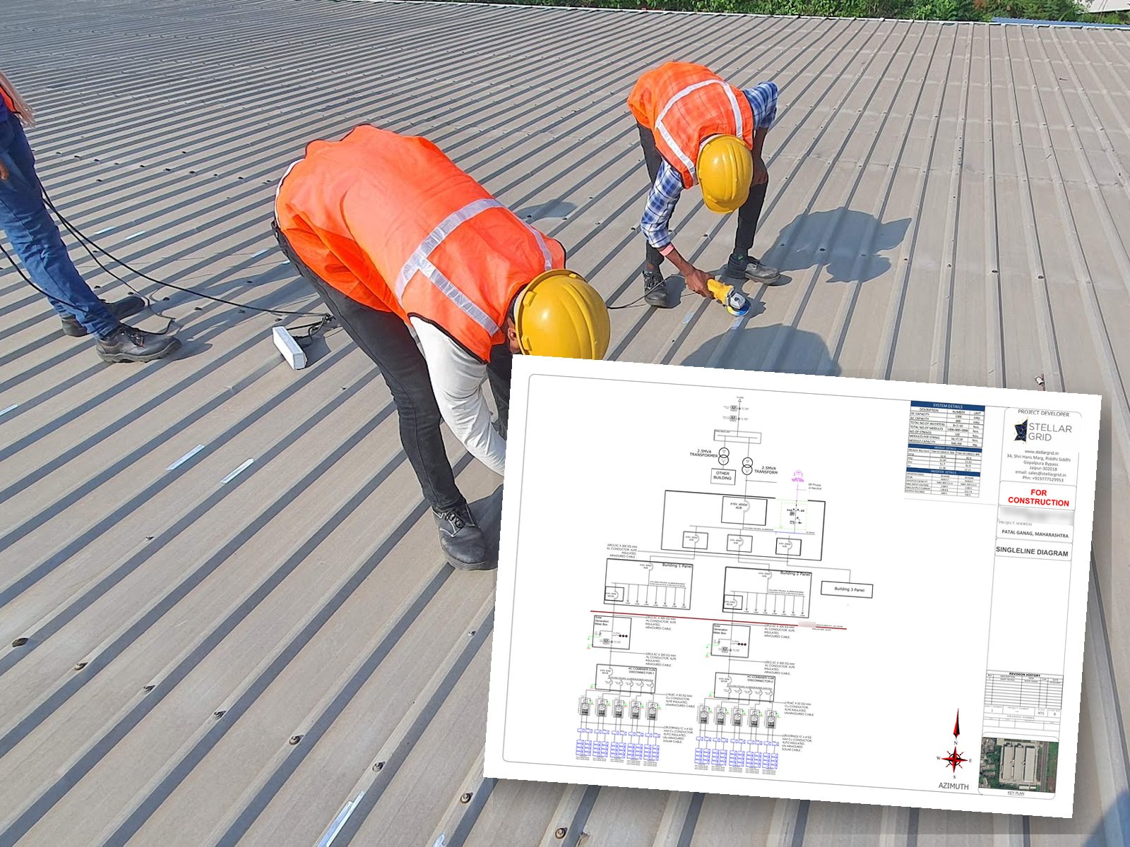
"Commissioned" should mean more than "the inverters switched on". A plant can produce power on day one while carrying reversed strings, damaged cells, loose connectors and earthing faults that will cost energy, and sometimes start fires, for years. The international reference for proving a plant was built correctly is IEC 62446-1, and its thermography companion, IEC 62446-3. Here is what a proper commissioning looks like, and what you should receive at handover.
IEC 62446-1 in brief
The standard defines the documentation, tests and inspections needed to hand over a grid-connected PV system. Tests are grouped into categories:
| Category | Tests | Applies to |
|---|---|---|
| Category 1 | Earth and bonding continuity, polarity, string open-circuit voltage, string current (short-circuit or operating), functional tests, insulation resistance of DC circuits | Every system |
| Category 2 | String I-V curve measurement, infrared (thermal) inspection | Larger and more complex systems, and good practice for every commercial plant |
| Additional tests | Earth electrode resistance, voltage to ground on resistive-earthed systems, shade evaluation, diode tests, wet insulation tests | As required by the project or investor |
What each test catches
- Continuity of protective earthing and bonding: frames or rails that are not actually connected to earth. See our guide to earthing and surge protection.
- Polarity: a string connected the wrong way round. Connecting a reversed string in parallel with others can damage equipment.
- String Voc: a missing or bypassed module in a string shows up as a voltage about one module short of its neighbours.
- String current: compares strings under the same conditions; a low string points to shading, damage or a wiring problem.
- Insulation resistance: damaged cable insulation, water in junction boxes or pinched cables, which are the precursors of earth faults and arcing.
- I-V curve tracing: measures the full current-voltage curve of each string and compares it with the expected curve. Steps and kinks reveal bypassed diodes, cracked cells, mismatch and series-resistance problems that a simple Voc test misses.
- Infrared thermography (IEC 62446-3): under steady irradiance (typically above 600 W/m²), a thermal camera reveals hotspots in cells, failed bypass diodes, overheating connectors and loose terminals in combiner boxes and inverters.
Electroluminescence: seeing inside the cells
Electroluminescence (EL) imaging is not part of IEC 62446-1 but is increasingly used at acceptance. A current is driven into a string at night and a special camera captures the light emitted by the cells. Microcracks, broken fingers and inactive cell areas show up clearly. EL is the best way to detect transport and installation damage before the module warranty clock starts, and it gives you a baseline to compare against in later years.
Performance ratio: proving the plant works as designed
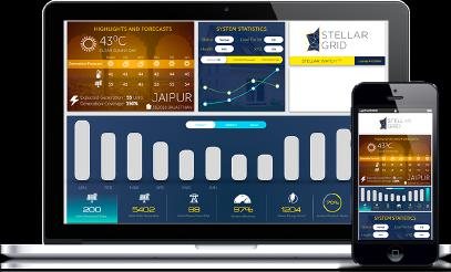
Individual tests show the plant is safe and built correctly. The performance ratio (PR) shows it performs. PR is the actual energy produced divided by the energy the array would theoretically produce at its rated efficiency given the measured irradiance. A well-built Indian rooftop plant typically runs at a PR of about 75–82% depending on climate and season. A performance acceptance test, usually over 7–30 days with an on-site irradiance sensor (pyranometer) and module temperature sensors, compares measured PR with the PR guaranteed in the contract.
This is why a plant needs proper weather instrumentation: without a calibrated irradiance sensor, there is no way to tell whether low generation is due to weather or a fault.
The handover file you should receive
- As-built single line diagram, layout and string diagrams
- Module, inverter and structure datasheets, with serial numbers mapped to their locations
- IEC 62446-1 test sheets for every string
- I-V curves and thermographic report (and EL images, if contracted)
- Earth resistance and insulation resistance records
- Protection settings for inverters, relays and any zero-export or DG controller
- Discom approvals, CEI/Electrical Inspectorate approval and net-metering agreement
- O&M manual, cleaning procedure and warranty documents
Why it matters later: commissioning records are the baseline for every warranty claim. If a module fails in year 6, the I-V curves, thermography and EL images from day one prove it was installed correctly and the defect is the manufacturer's.
Testing doesn't stop at handover
IEC 62446-2 covers maintenance. A sensible routine for a commercial plant is a monthly review of monitoring and PR, an annual thermographic survey before the monsoon, annual insulation resistance and earth pit tests, torque checks on terminals, and I-V curve tracing whenever monitoring flags an underperforming string.
Our O&M service covers routine inspections like these. If your plant was handed over without any of the documents above, we can test it and build the file.
Sources and further reading
- Hioki: maintenance of PV systems according to IEC 62446-1
- Fluke / pv magazine: PV commissioning and IEC 62446 testing
- prEN IEC 62446-1:2025 (revision in progress)
Standards and regulations change. Check the current edition and your state regulator before relying on any figure for a specific project.